PROCEDURALLY GENERATED 3D MODELS OF RAISED FIELD AGRICULTURE IN THE BOLIVIAN AMAZON
Figures
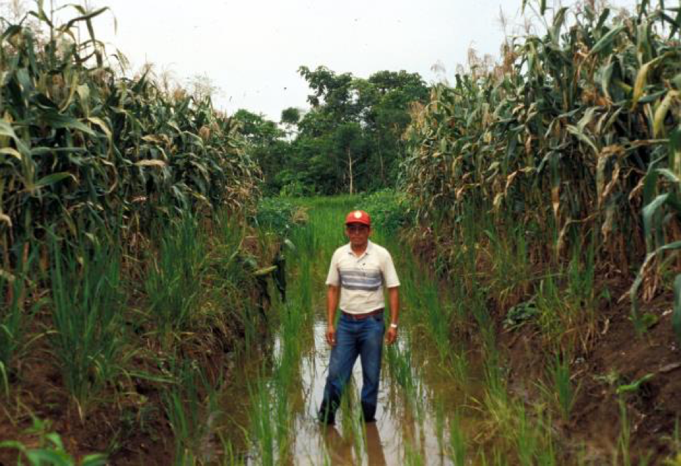
Figure 1: Experimental raised fields with maize in 1993, Community of Bermeo, Bolivia (photograph by Clark Erickson).
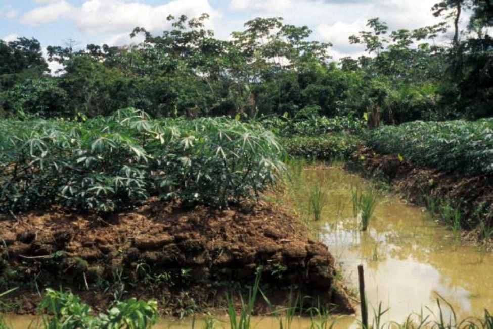
Figure 2: Experimental raised fields with manioc in 1993, Community of Bermeo, Bolivia (photograph by Clark Erickson).

Figure 3: Experimental raised field with maize in 1993, Community of Bermeo, Bolivia (photograph by Clark Erickson).
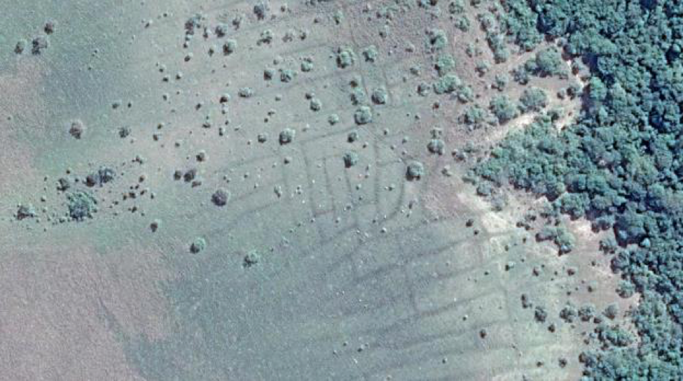
Figure 4: Raised field platforms (light green) and canals (light gray) near Orobayaya, Bolivia (Google Earth—see style guide for how to format and cite Google Earth images).
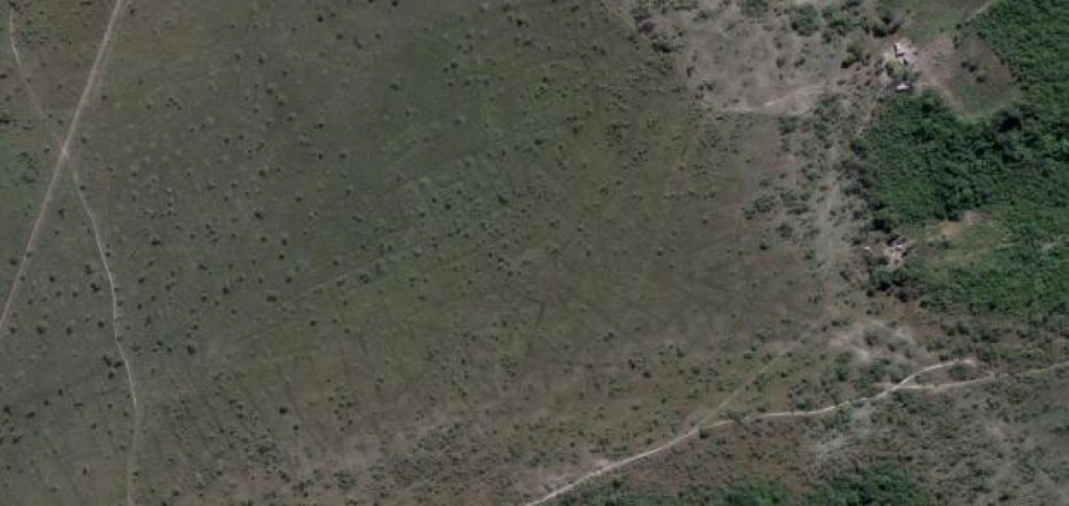
Figure 5: Raised field platforms (light green) and canals (light gray) near Orobayaya, Bolivia.
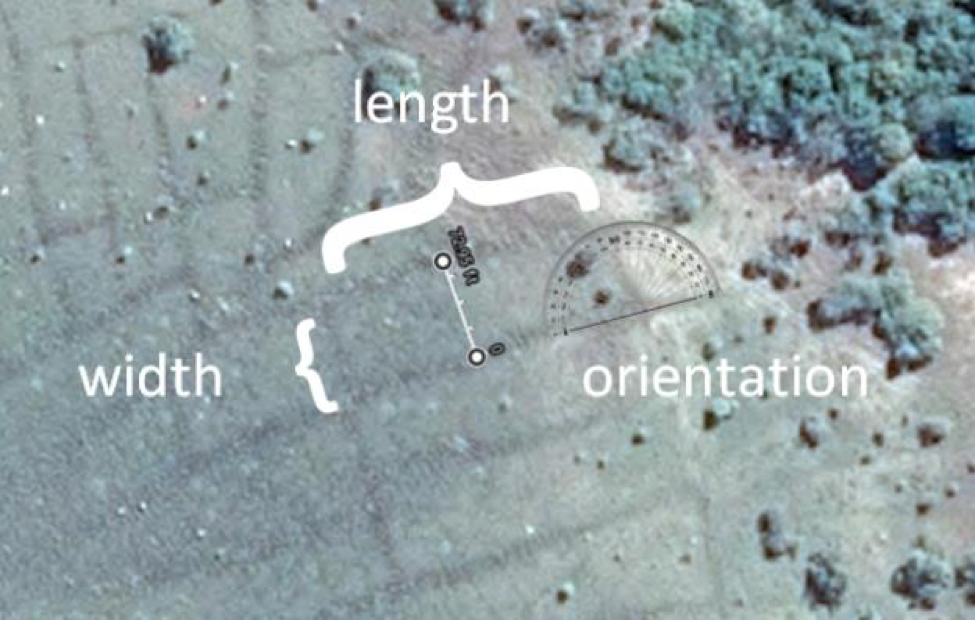
Figure 6: Diagram of the measurements taken of a raised field.
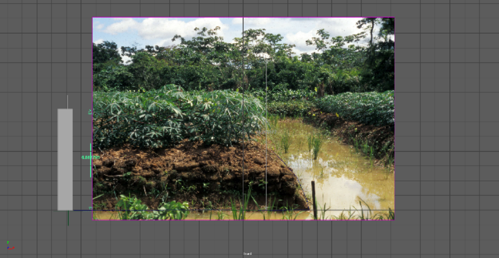
Figure 7: Image of experimental raised field within Maya software to guide modeling.
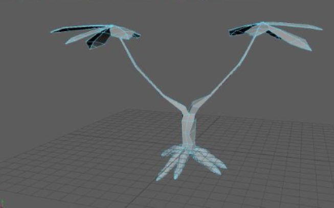
Figure 8: Manioc low-poly 3D model in Maya software
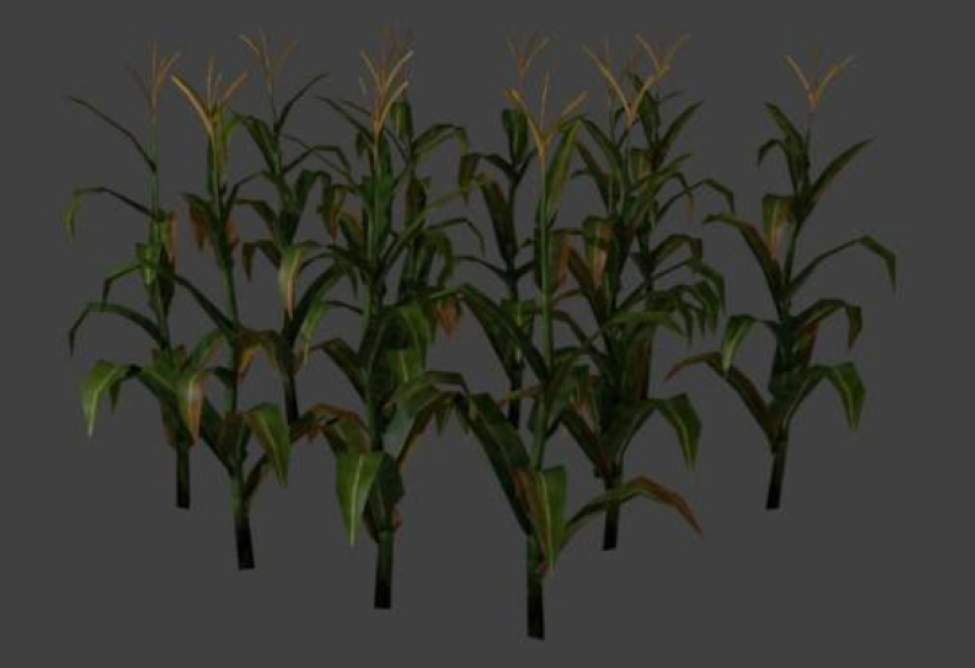
Figure 9: Maize low-poly 3D model in Maya software.
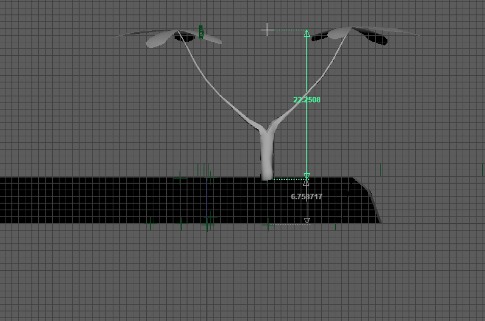
Figure 10: Manioc scaled relative to a raised field.
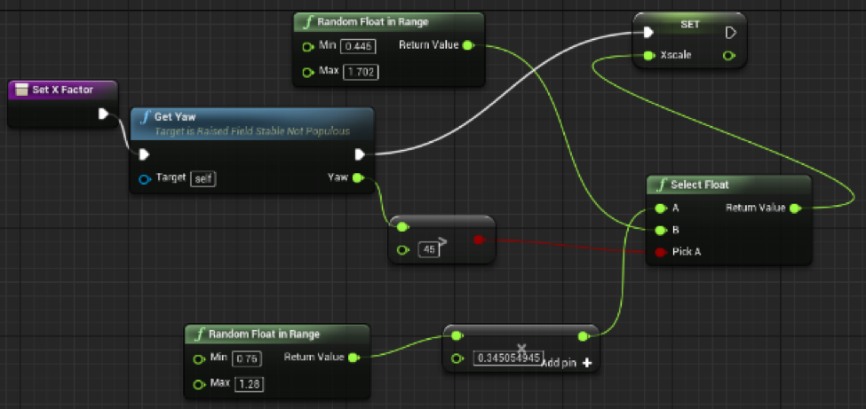
Figure 11: Blueprints logic used to scale raised fields for procedural generation modeling in Unreal Engine.
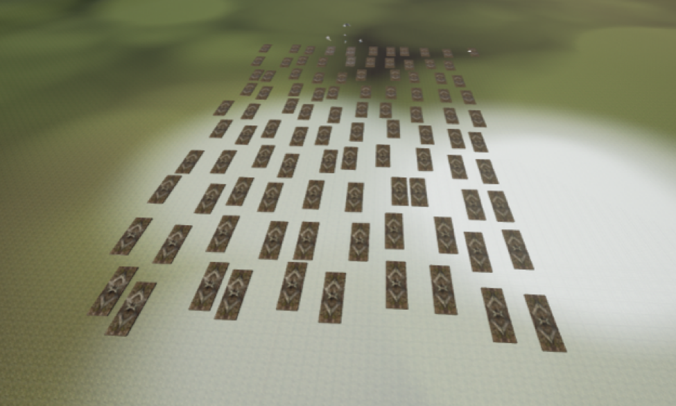
Figure 12: Procedurally generated raised fields in grid fashion.
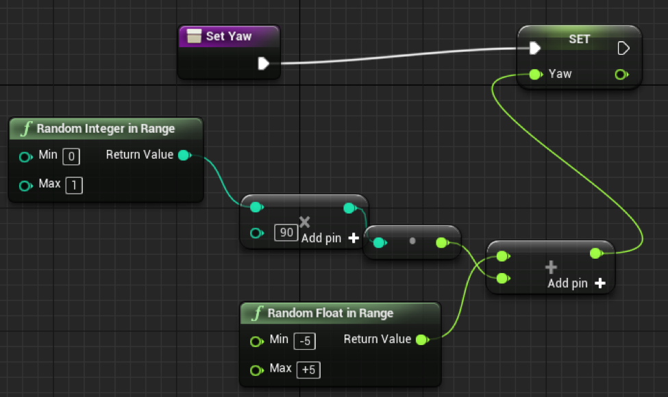
Figure 13: Blueprints logic used to set random orientation to a raised field.
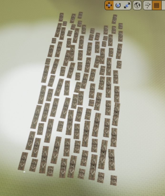
Figure 14: Raised fields procedurally generated with random orientation within a grid pattern.
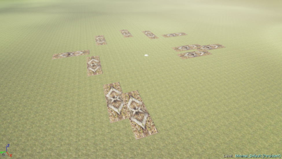
Figure 15: Procedurally generated raised fields with random locations but overlapping.

Figure 16: Blueprints logic used to detect and prevent overlapping raised fields.

Figure 17: Raised field populated with manioc in rows.
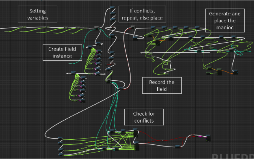
Figure 18: Main function in Blueprints with major subfunctions labeled.
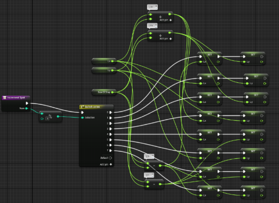
Figure 19: Blueprints logic used to randomly place the field.

Figure 20: Blueprints logic used to set the yaw of the raised field.

Figure 21: Blueprints logic used to set scale of the raised field.
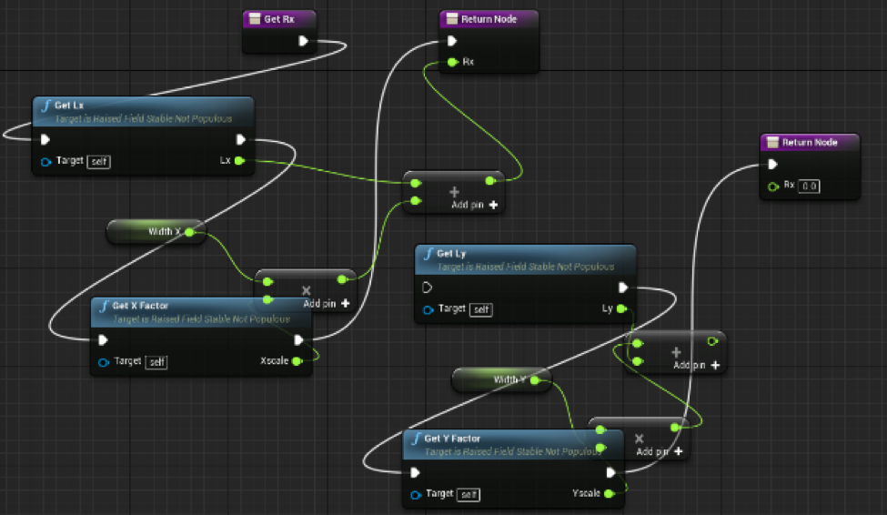
Figure 22: Blueprints logic used to determine the bounding box of a raised field for overlap detection and prevention.
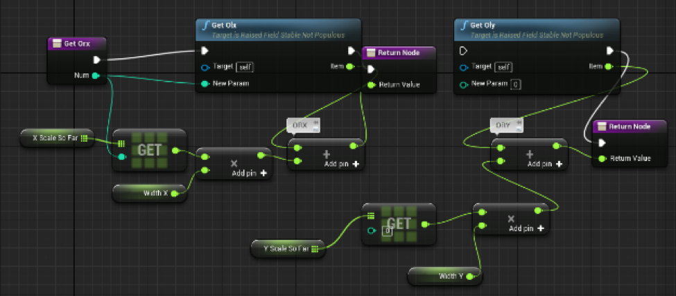
Figure 23: Blueprints logic used to determine bounding box of all raised fields placed.
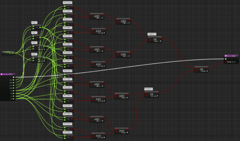
Figure 24: Blueprints logic used to detect overlapping raised fields.
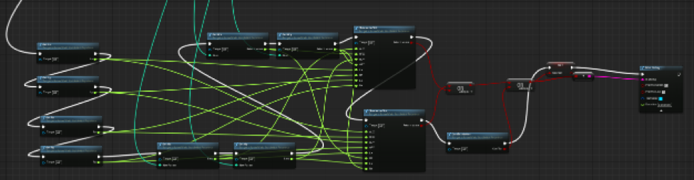
Figure 25: Blueprints logic used to prevent fields from overlapping.
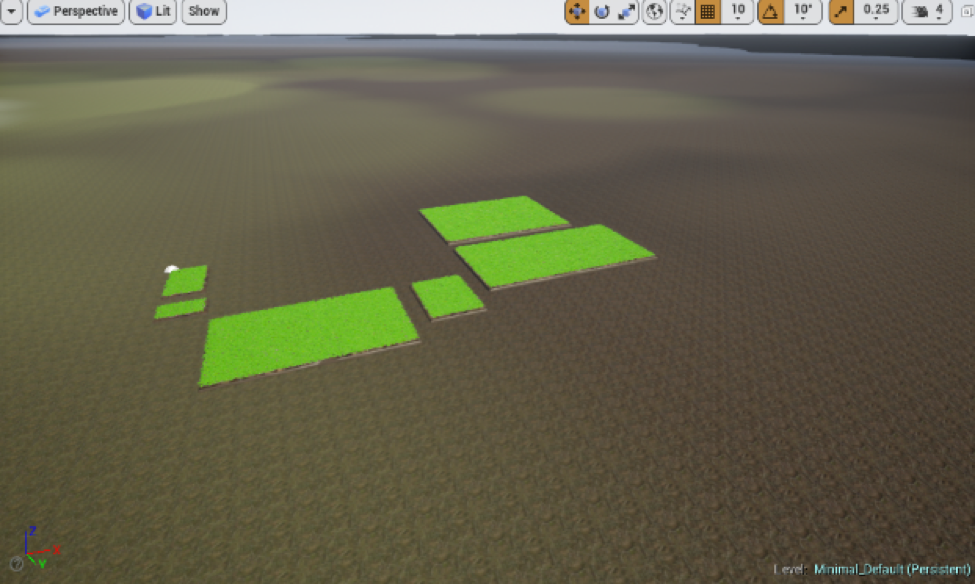
Figure 26: Procedurally generated manioc foliage on 6 raised fields.
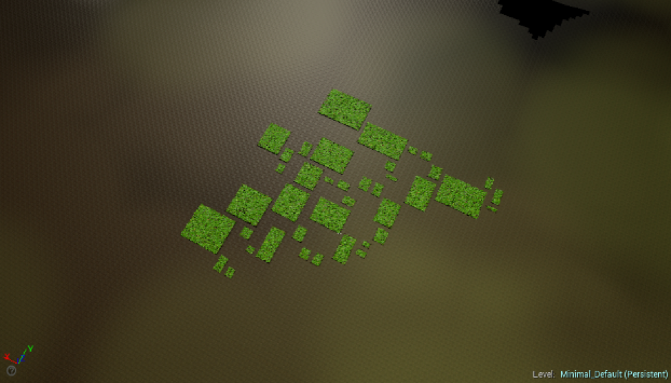
Figure 27: Procedurally generated manioc foliage on 40 raised fields.
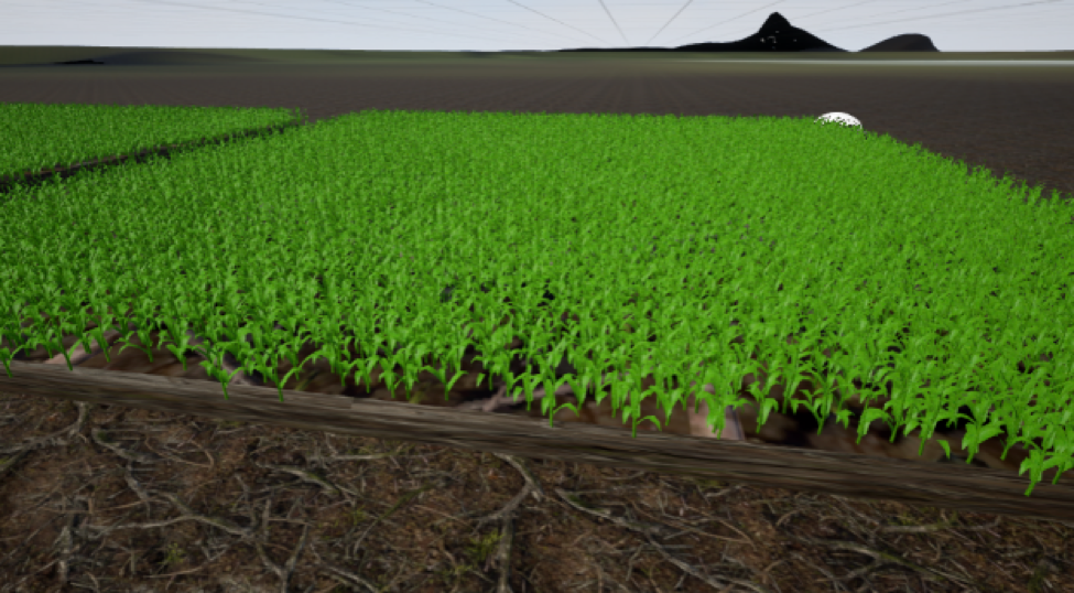
Figure 28: Procedurally generated maize foliage on 2 raised fields.
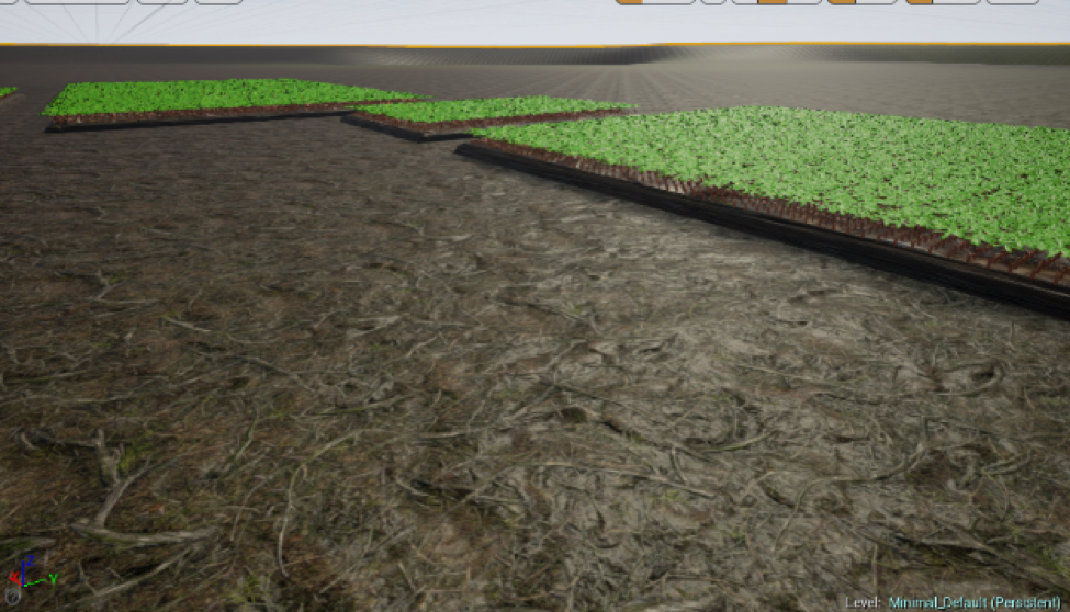
Figure 29: Procedurally generated manioc foliage on 3 raised fields.
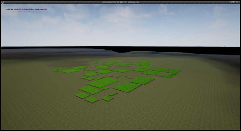
Figure 30: Procedurally generated foliage and raised fields.