Pottery Production at the Ceremonial Site of Pachacamac: A Visualization of the Mold-Making Technique
3D Models
Figures
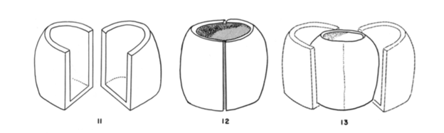
Figure 1: Mold of a small pottery vessel. Image via Donnan, 1965, Figures 11, 12, 13, p.23.
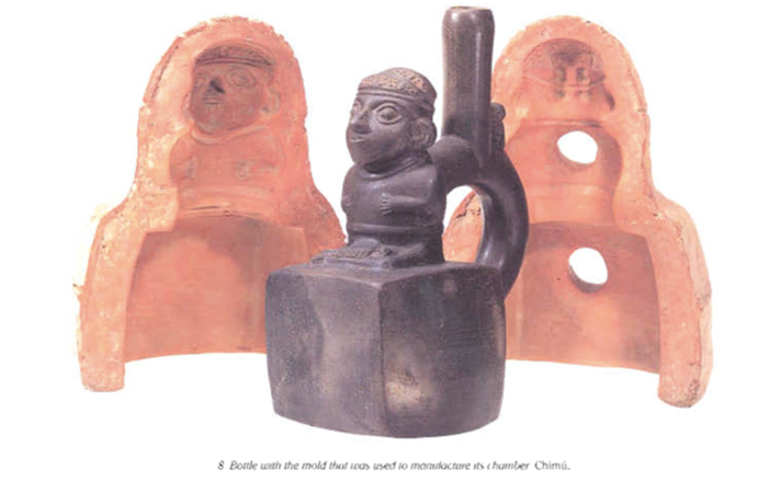
Figure 2: Ornate bottle with the mold. Image via Donnan 1992, Figure 8, p.15.
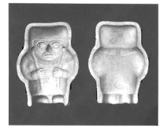
Figure 3: A small Moche figurine mold. Image via Donnan 1992, Figure 11, p.17.
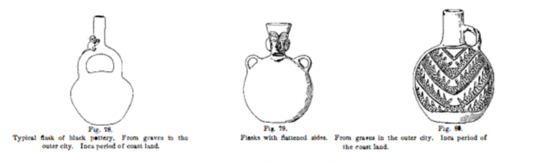
Figure 4: A range of detailed modeling created by the mold technique, seen in vessel from Pachacamac now at the Penn Museum. Image via Uhle [1903] 1991, Figure 78, 79, 80, p.65.

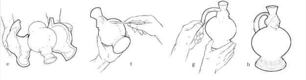
Figure 5: Reconstruction of the process of forming a pottery vessel in the mold-making technique. This illustrates how pottery was made using two-piece molds and hand modeling to attached the handle piece. Image via Donnan 1992, Figure e,f,g,h. p.17.
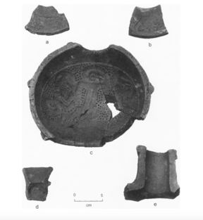
Figure 6: A pottery vessel mold reconstructed from excavated fragments. The mold shows a section of vessel spot/neck. Image via Donnan 1997, Figure 4, p.34.
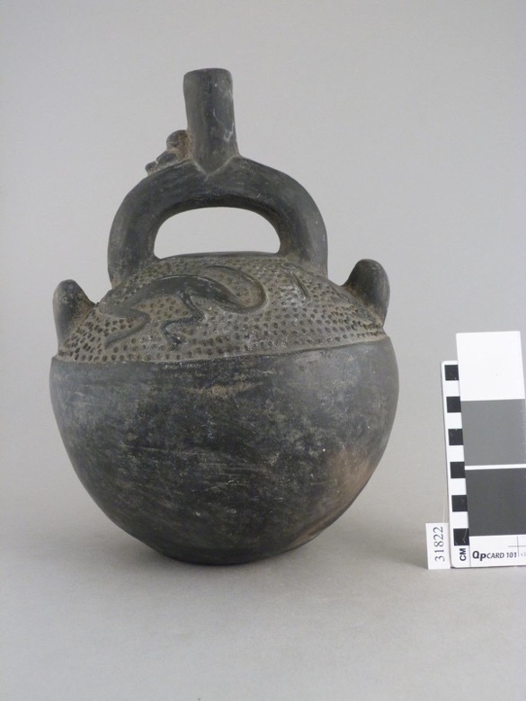
Figure 7: Ceramic stirrup-spout bottle from Pachacamac, at the Penn Musuem (object 31822). Image via Penn Museum website.
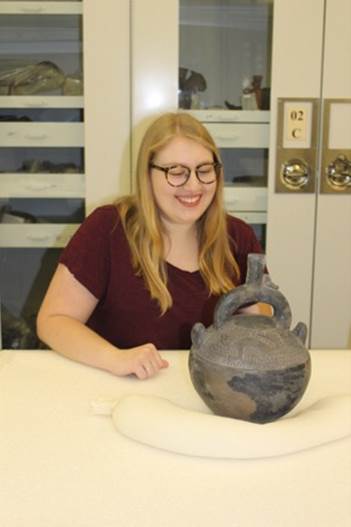
Figure 8: Delaney Keenan analyzing the object at the Penn Museum. Photo by Clark Erickson.
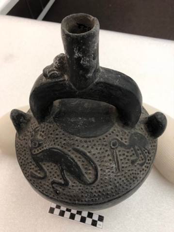
Figure 9: Image of the zoomorphic iconography top of the vessel (cat, pelican, and monkey).
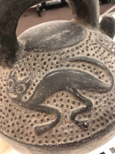
Figure 10: Detail image of the vessel iconography and dot texture.
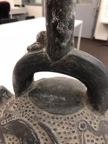
Figure 11: Detail of the handle to use for modeling reference.
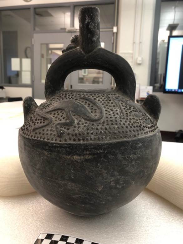
Figure 12: Modeling reference image.
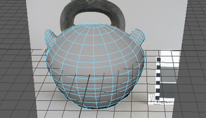
Figure 13: Round body of the vessel after I traced the edge using the Bezier Curve tool.
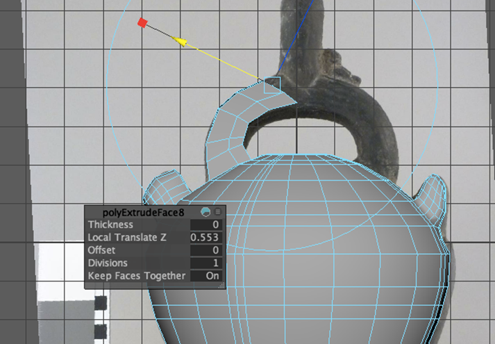
Figure 14: Extrusions to form the handle.
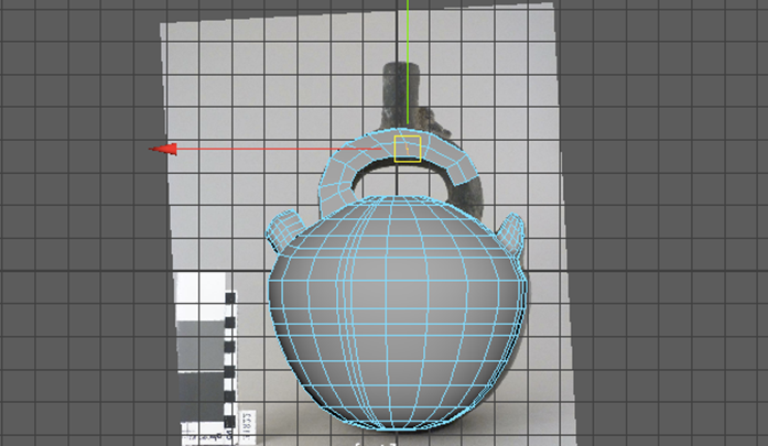
Figure 15: Extruding and modeling the handle.
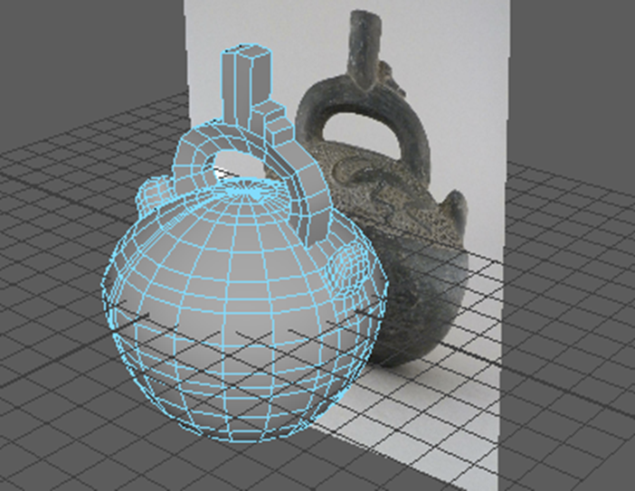
Figure 16: Extruding the spout.
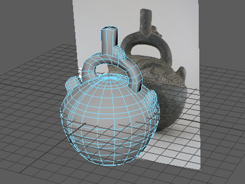
Figure 17: Smoothing of the handle elements.
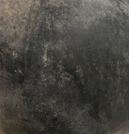
Figure 18: Reference image for the surface color.
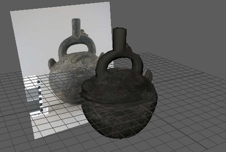
Figure 19: Reference photograph used to match the vessel surface color.
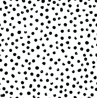
Figure 20: The polka dot texture I used to help create the bump map needed for the top half of the vessel. Image via stockphotos.

Figure 21: Working with PB-materials and lighting.
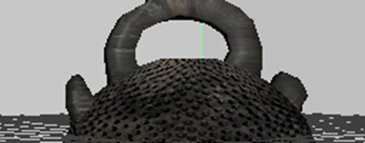
Figure 22: Detail of the bump texture applied to the model.
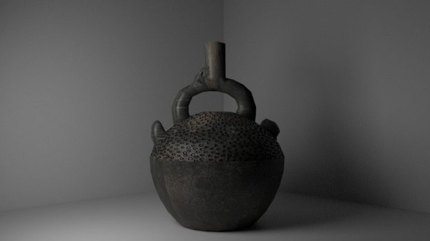
Figure 23: First image render.
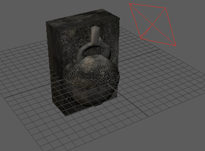
Figure 24: Pottery vessel attached to a mold. Booleans –difference function failed.
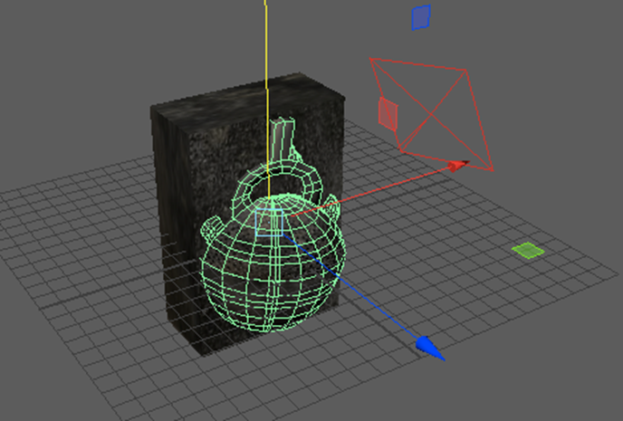
Figure 25: Duplicating vessel in preparation for OBJ file export.
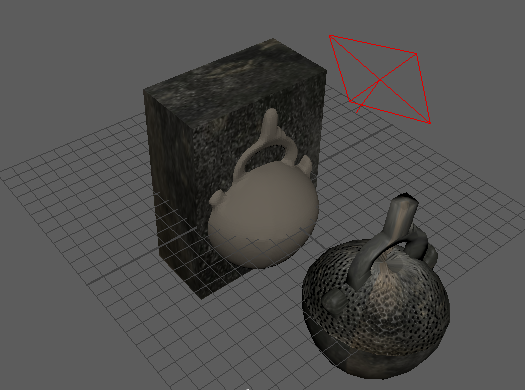
Figure 26: Copy of vessel from ZBrush attached to the mold.
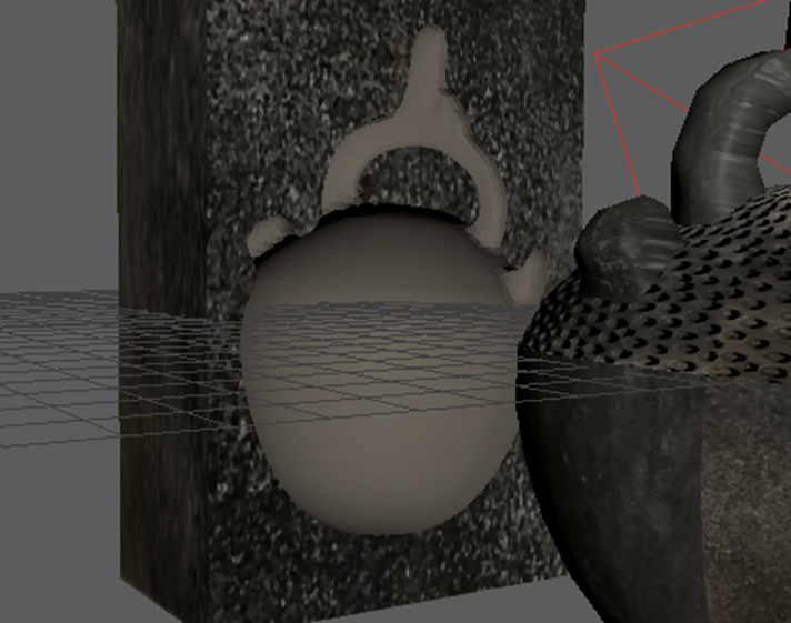
Figure 27: Detail of the negative space created by performing the Booleans-difference function on the model.
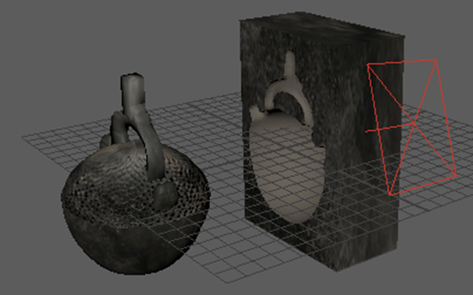
Figure 28: Another view of the molded space.
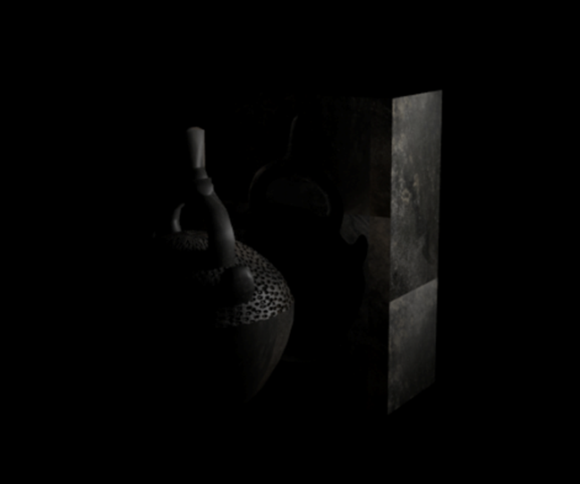
Figure 29: Render without added lighting.
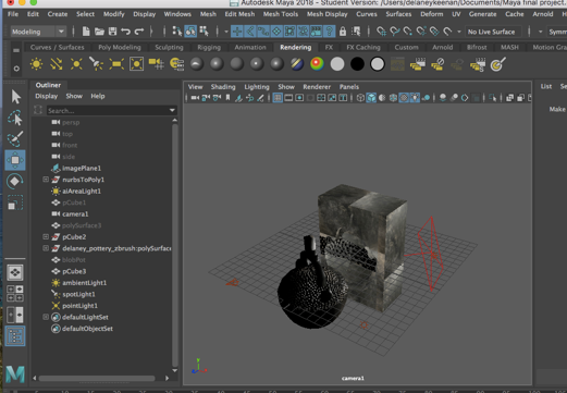
Figure 30: Adding lighting to the model.
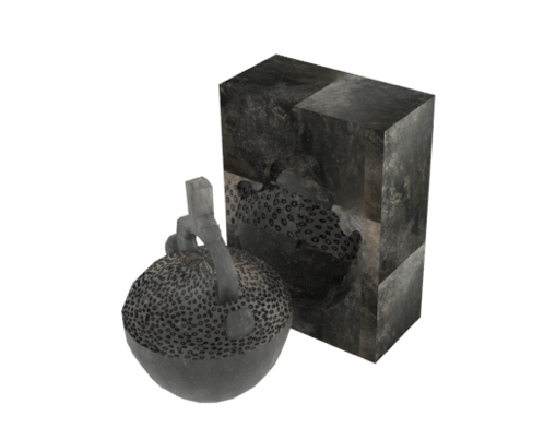
Figure 31: The model with lighting.
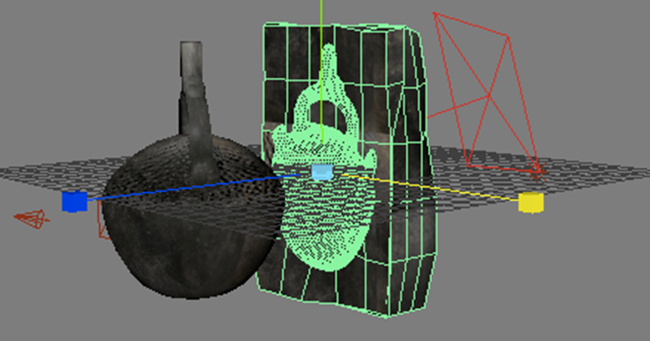
Figure 32: Adjusting the shape of the mold to appear with rounded edges.

Figure 33: Transforming the edges and faces to appear more natural.
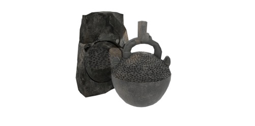
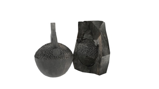
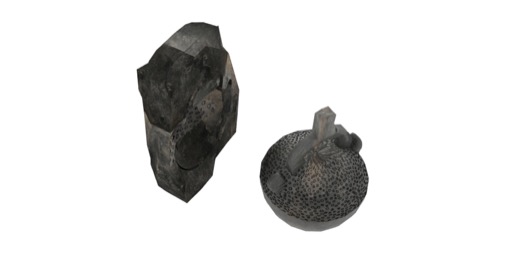
Figure 34: Different perspectives of the vessel and mold after render.
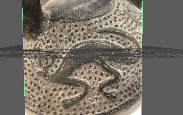
Figure 35: Reference image as a Free Image Plane to trace the animals for the top of the vessel.

Figure 38: Reference image of the bump texture.

Figure 39: Detail of the alignment of the raised dot design and body.
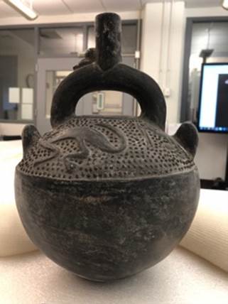
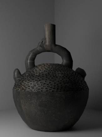
Figure 40: Side by side comparison of reference image and the 3D model.